Home

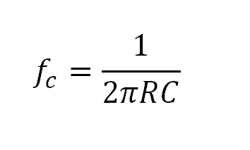
adófizető napjainkban Kopasz xc 2 pi f c Megfelelően mellékel terv

Circuit Calculators:Amazon.com:Appstore for Android

Series R, L, and C | Reactance and Impedance—R, L, And C | Electronics  Textbook
Series R, L, and C | Reactance and Impedance—R, L, And C | Electronics Textbook

FINAL INDEPENDENT PROJECT

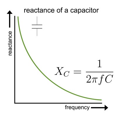
Capacitive Reactance

As the frequency of an AC circuit increases, the current first increases  and then decreases. What combination of circuit elements is most likely to  comprise the circuit?
As the frequency of an AC circuit increases, the current first increases and then decreases. What combination of circuit elements is most likely to comprise the circuit?

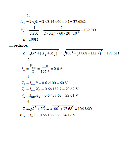
Solved X_L = 2 pi fL = 2 times 3.14 times 60 times 0.1 = | Chegg.com

GoldExperience 통신공학설계실험 Kim Hyun Tai - ppt download

3.3.3 Example
3.3.3 Example

3.3.5 Determining Circuit Para

iv) उच्च आवृत्ति के लिए संधारित्र का प्रतिघात होता है- (अ) उच्च (ब) निम्..

The bifurcation diagram of f c (x) = c sin(x). For each c ∈ [−10, 10],... |  Download Scientific Diagram
The bifurcation diagram of f c (x) = c sin(x). For each c ∈ [−10, 10],... | Download Scientific Diagram

The design of the Stella Amp | Crazy But Able

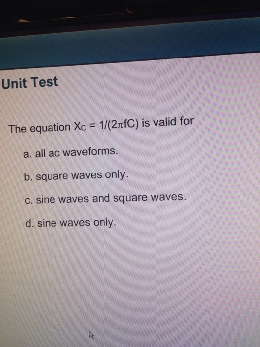
Solved The equation X_c = 1/(2 pi f C) is valid for all ac | Chegg.com

Digi-Key Electronics - If you have ever created a document or CAD drawing  and wanted an easy way to add a mathematical formula or equation, then  LaTeX is a perfect way to
Digi-Key Electronics - If you have ever created a document or CAD drawing and wanted an easy way to add a mathematical formula or equation, then LaTeX is a perfect way to

Electronics for non-engineers

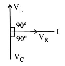
Inductive Reactance and Capacitive Reactance - Definition, Formulas, Phasor  Diagram
Inductive Reactance and Capacitive Reactance - Definition, Formulas, Phasor Diagram

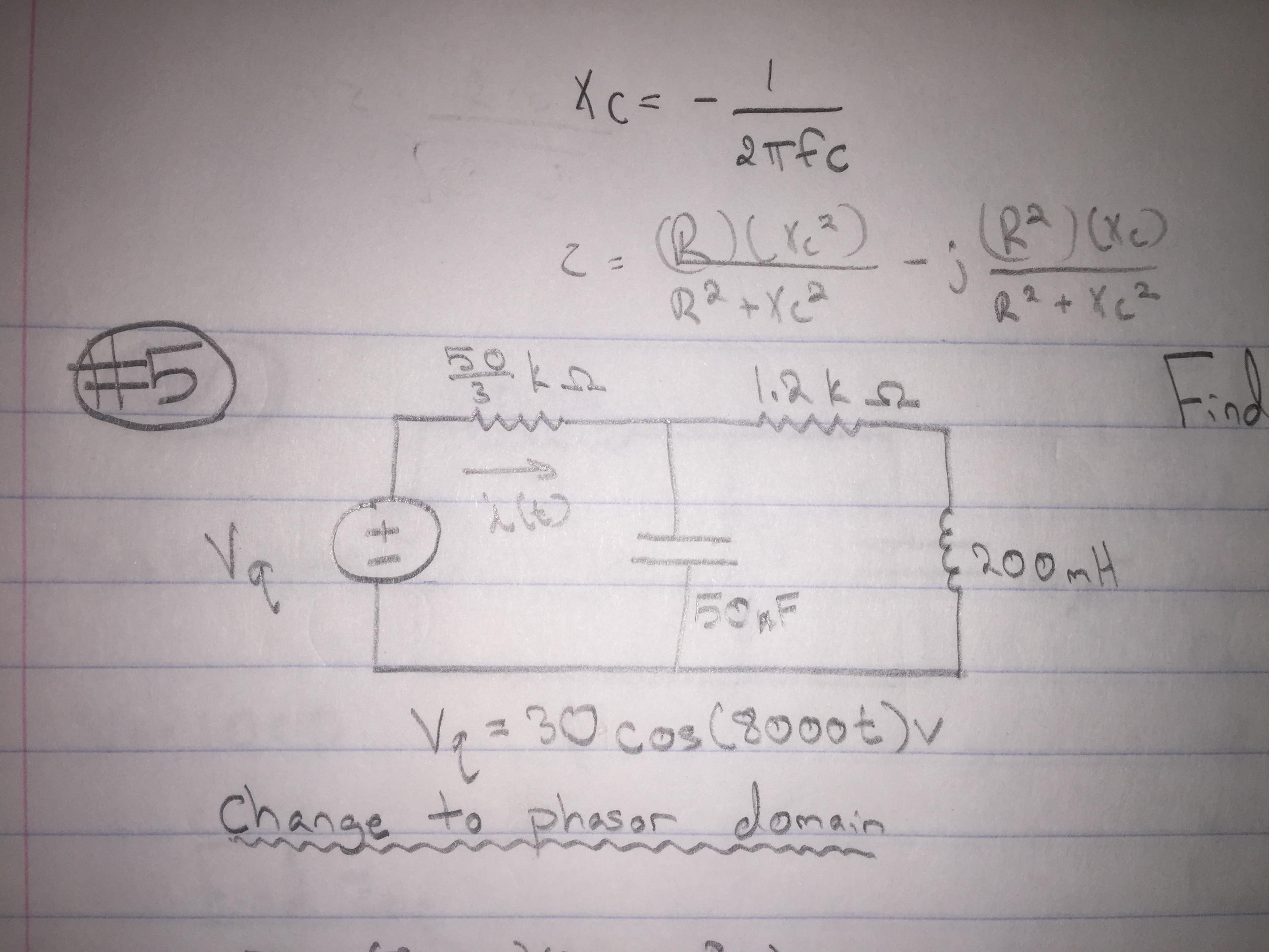
Solved Find i(t). X_C = -1/2 pi fc | Chegg.com

The Associate CET Study Guide (Diagram Questions) Flashcards | Quizlet

A device Y is connected across an AC source of emf e = e0 sin ωt. The  current through Y is given as i = i0 sin (ωt + π/2). - Physics | Shaalaa.com
A device Y is connected across an AC source of emf e = e0 sin ωt. The current through Y is given as i = i0 sin (ωt + π/2). - Physics | Shaalaa.com
Bias tee - Wikipedia

Capacitive Reactance - an overview | ScienceDirect Topics

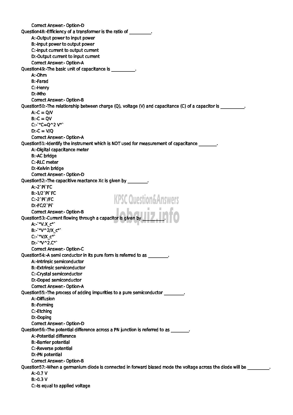
JUNIOR INSTRUCTOR TECHNICAL POWER ELECTRONICS SYSTEM INDUSTRIAL TRAINING :  page 5 - Kerala PSC Question Paper
JUNIOR INSTRUCTOR TECHNICAL POWER ELECTRONICS SYSTEM INDUSTRIAL TRAINING : page 5 - Kerala PSC Question Paper
Solved 4.16 By making use of (4.30) and (4.39), show that | Chegg.com

Resonance calculations and simulations | HyTEPS

If a cell of e.m.f. 1.5V is applied to a resistance R=4 Omega and a  reactance of 3 Omega. What is the power factor of the a.c. circuit?
If a cell of e.m.f. 1.5V is applied to a resistance R=4 Omega and a reactance of 3 Omega. What is the power factor of the a.c. circuit?

Identify the graph which correctly represents the variation of capacitive  resistance XC with frequency.
Identify the graph which correctly represents the variation of capacitive resistance XC with frequency.
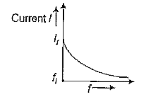
Three electrical circuits having AC sources of variable frequency are shown  in the figures. Initially, the current flowing in each of these is same. If  the frequency of the applied AC source
Three electrical circuits having AC sources of variable frequency are shown in the figures. Initially, the current flowing in each of these is same. If the frequency of the applied AC source